チュートリアル:ディレイラインによる弦モデルの作成
物理モデリングによるリアルな弦モデルを実装します。ステレオサウンドフィールドで複雑なエコーパターンを作成するためにディレイラインを組み込みます。
レベル: 上級
プラットフォーム: Windows, macOS, Linux
プラグイン形式: VST, AU, Standalone
クラス: dsp::ProcessorChain, dsp::Gain, dsp::Oscillator, dsp::Convolution, dsp::WaveShaper, dsp::Reverb
このプロジェクトにはC++14機能をサポートするコンパイラが必要です。最新バージョンのXcodeとVisual Studioにはこのサポートが含まれています。
はじめに
このチュートリアルはチュートリアル:ウェーブシェイピングとコンボリューションによるディストーションの追加からの続きです。まだ読んでいない場合は、まずそのチュートリアルを読んでください。
このチュートリアルのデモプロジェクトをこちらからダウンロードしてください:PIP | ZIP。プロジェクトを解凍し、最初のヘッダファイルをProjucerで開いてください。
このプロジェクトのPIPバージョンを使用する場合は、Resourcesフォルダを生成されたProjucerプロジェクトにコピーしてください。
この手順でサポートが必要な場合は、チュートリアル:Projucer Part 1: Projucerを始めようを参照してください。
デモプロジェクト
このプロジェクトはプラグインとして構想されていますが、IDEで適切なデプロイメントターゲットを選択することでスタンドアロンアプリケーションとして実行できます。Xcodeでは、以下のスクリーンショットに示すように、メインウィンドウの左上隅でターゲットを変更できます:

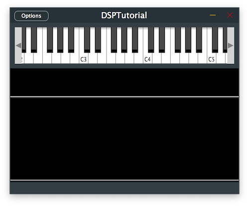
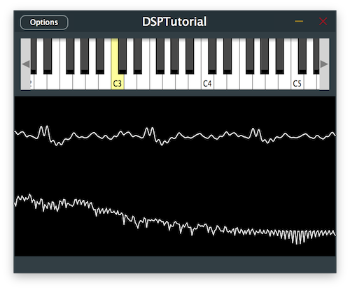
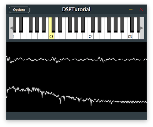
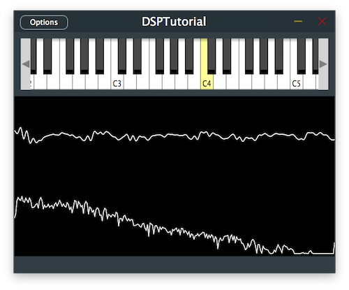
デモプロジェクトは、プラグインの上半分に画面上のMIDIキーボード、下半分にオシロスコープを通じた信号の視覚的表現を提供します。現在、キーを押すと、プラグインはいくつかのリバーブとディストーションが追加された基本的なオシレーターサウンドを出力します。
AudioEngineクラスでエフェクトプロセッサをコメントアウトすることで、チュートリアルの各ステップでの変化を明確に聴くためにエフェクトを削除してください。

MIDIコントローラーをお持ちの場合は、このチュートリアル全体で画面上のキーボードの代わりに接続することもできます。
イントロダクション
このチュートリアルでは、異なる方法で信号処理を可能にする2つの新しいDSPコンセプトを紹介します:ディレイラインと物理モデリング。
まず、このDSP用語を定義しましょう。
ディレイラインとは?
ディレイラインは、残響空間のシミュレーション、サウンド合成、フィルタ実装、ディレイ、コーラス、フェイザー、フランジャーなどのクラシックな時間ベースのエフェクトを含む幅広いアプリケーションで使用できるDSPの基本ツールです。
基本的に、ディレイラインは非常にシンプルで、特定の信号をサンプル数だけ遅延させることができます。複数のディレイラインを使用し、異なる間隔で個別の信号を足し合わせることで、デジタル信号処理の大部分を作成できます。
アナログドメインでは、ディレイラインは波の伝播を遅延させるためにスプリングなどの実際の物理的な拡張を導入することで実装されていました。デジタルドメインでは、ディレイラインは多くの場合、サーキュラーバッファと呼ばれるデータ構造を使用して実装されます。
サーキュラーバッファは、本質的に、サンプルバッファブロックのサイズに一致するサーキュラーデータ構造を作成するためにインデックスが自身を巻き付ける配列として実装できます。これにより、前のブロックに含まれるすべてのサンプルを現在のブロックでアクセスできるように保存し、次の反復のために現在のサンプルブロックによって上書きされるだけです。
このチュートリアルでは、ディレイラインを実装する方法としてサーキュラーバッファを見ていきます。
物理モデリングとは?
物理モデリングは、サウンドを生成するために数学的および物理的モデルに依存するサウンド合成方法を指します。他の合成技術とは異なり、出発点としてサンプルを使用せず、材料の研究を通じて物理的な意味でサウンドがどのように生成されるかに焦点を当てています。
これらのモデルの1つは、音波が管やパイプを通じて伝播する物理モデルに基づくデジタルウェーブガイドと呼ばれます。境界に対するこれらの波の反射は、ディレイラインを使用して効率的に計算でき、そのため弦などの楽器のサウンドの多くはこのモデルを使用して生成できます。
ウェーブガイド弦モデル
簡単に言えば、ウェーブガイド弦モデルは、振動する弦を反対方向に移動し、2つの端点で跳ね返る2つの波を使用してモデル化できるという概念に基づいています。これら2つの波を足し合わせた組み合わせは、最終的に弾かれた弦の理想的な動きをシミュレートし、これらは2つのディレイライン(順方向と逆方向のディレイライン)を使用して実装できます。
ただし、この弦の理想的なモデルは、減衰が考慮されていないため、現在の状態では決して静止しません。したがって、波が境界で方向を変えて極性が反転するとき、波の変位を減らすために減衰係数を組み込むことができます。
このモデルで考慮すべき他の変数は、弦の弾く位置と振動する弦のサウンドをピックアップする位置です。したがって、2つの波が伝播する弾く位置と、空間内の特定の位置からサウンドを聴くようなピックアップ位置を統合する必要があります。
最後に、物理的な弦で発生する自然現象は、高周波数が低周波数よりも速く減衰することです。これは、境界の一端にローパスフィルターを追加することで、減衰時間のこの不一致をシミュレートするモデルに簡単に統合できます。
このチュートリアルでは、ディレイラインを使用して、接続された弦の境界で反射する波で弾かれた弦をシミュレートするデジタルウェーブガイドモデルを実装します。
ディレイラインの実装
ベクトルを使用してサーキュラーバッファとしてシンプルなディレイラインを実装することから始めましょう。
DelayLineクラスでは、size()とresize()メソッド、clear()関数、バッファ内の最も古いサンプルを取得するback()関数など、実装を容易にするためのいくつかの自明なヘルパー関数が既に定義されています。
まず、最も最近追加されたサンプルを上書きして新しいサンプルを追加するpush()関数を実装し[1]、サーキュラーバッファのサイズでインデックスをラップすることで最も古いインデックス変数を更新します[2]:
void push (Type valueToAdd) noexcept
{
    rawData[leastRecentIndex] = valueToAdd; // [1]
    leastRecentIndex = leastRecentIndex == 0 ? size() - 1 : leastRecentIndex - 1; // [2]
}
次に、関数引数で指定されたオフセットに位置するサンプルを返すget()関数を完成させ、インデックスがベクトルを巻き付けることを確認します[3]。ここで、遅延がバッファのサイズを超えないことを確認します。
Type get (size_t delayInSamples) const noexcept
{
    jassert (delayInSamples >= 0 && delayInSamples < size());

    return rawData[(leastRecentIndex + 1 + delayInSamples) % size()]; // [3]
}
次に、関数引数で指定されたオフセットにサンプルを割り当てるset()関数を埋め、インデックスがベクトルを巻き付けることを確認します[4]。ここでも、遅延がバッファのサイズを超えないことを確認します。
void set (size_t delayInSamples, Type newValue) noexcept
{
    jassert (delayInSamples >= 0 && delayInSamples < size());

    rawData[(leastRecentIndex + 1 + delayInSamples) % size()] = newValue; // [4]
}
これでシンプルなディレイラインの実装が完了しました。
ディレイエフェクトの組み込み
基本的なディレイラインクラスが実装されたので、信号チェーンにステレオディレイエフェクトを組み込みましょう。
Delayクラスでは、ディレイエフェクトの動作を変更するために調整できる複数のパラメータがあり、これらには個々のチャンネルのディレイタイム、許可される最大ディレイタイム、エフェクトのドライ/ウェットレベル、フィードバック量が含まれます。
これらのパラメータとディレイラインの実装を使用して、必要に応じて幅広いディレイエフェクトを作成できますが、コンストラクタで定義されたデフォルトパラメータから始めましょう:
{
public:
    //==============================================================================
    Delay()
    {
        setMaxDelayTime (2.0f);
        setDelayTime (0, 0.7f);
        setDelayTime (1, 0.5f);
        setWetLevel (0.8f);
        setFeedback (0.5f);
    }
これらのヘルパー関数は主に対応するメンバー変数を設定してパラメータを保存しますが、一部はパラメータの変更に対応するためにデータ構造のリサイズも必要とします。
そのようなケースの1つは、以下に定義されたsetMaxDelayTime()関数で、updateDelayLineSize()ヘルパー関数を呼び出します[1]:
void setMaxDelayTime (Type newValue)
{
    jassert (newValue > Type (0));
    maxDelayTime = newValue;
    updateDelayLineSize(); // [1]
}
ベクトルをリサイズすることで、すべてのディレイラインのサーキュラーバッファが最大ディレイタイムまでの任意のディレイタイムに対応できる十分な大きさであることを確認する以下の関数を完成させます[2]:
void updateDelayLineSize()
{
    auto delayLineSizeSamples = (size_t) std::ceil (maxDelayTime * sampleRate);

    for (auto& dline : delayLines)
        dline.resize (delayLineSizeSamples); // [2]
}
もう1つの注目すべきケースは、パラメータの変更がupdateDelayTime()ヘルパー関数の呼び出しを引き起こす個々のチャンネルのsetDelayTime()関数です[3]:
void setDelayTime (size_t channel, Type newValue)
{
    if (channel >= getNumChannels())
    {
        jassertfalse;
        return;
    }

    jassert (newValue >= Type (0));
    delayTimes[channel] = newValue;

    updateDelayTime(); // [3]
}
新しいパラメータ変更に基づいてすべてのチャンネルのサンプル単位のディレイタイムを再計算するこのヘルパー関数を実装します[4]:
void updateDelayTime() noexcept
{
    for (size_t ch = 0; ch < maxNumChannels; ++ch)
        delayTimesSample[ch] = (size_t) juce::roundToInt (delayTimes[ch] * sampleRate);
}
reset()関数で、このチュートリアルの次のセクションで使用する各チャンネルのフィルターをリセットし[5]、ディレイラインに残っている古いサンプルをクリアします[6]:
void reset() noexcept
{
    for (auto& f : filters)
        f.reset(); // [5]

    for (auto& dline : delayLines)
        dline.clear(); // [6]
}
prepare()関数で、サンプルブロック間でサンプルレートが変更された場合に備えて、ディレイラインのサイズ[7]とサンプル単位のディレイタイム[8]がまだ正しいことを確認し、今のところローパスフィルターでフィルターを初期化します[9]:
void prepare (const juce::dsp::ProcessSpec& spec)
{
    jassert (spec.numChannels <= maxNumChannels);
    sampleRate = (Type) spec.sampleRate;
    updateDelayLineSize(); // [7]
    updateDelayTime(); // [8]

    filterCoefs = juce::dsp::IIR::Coefficients<Type>::makeFirstOrderLowPass (sampleRate, Type (1e3)); // [9]

    for (auto& f : filters)
    {
        f.prepare (spec);
        f.coefficients = filterCoefs;
    }
}
では、ディレイエフェクトを実際に実装するためにprocess()関数を処理しましょう:
template <typename ProcessContext>
void process (const ProcessContext& context) noexcept
{
    auto& inputBlock = context.getInputBlock();
    auto& outputBlock = context.getOutputBlock();
    auto numSamples = outputBlock.getNumSamples();
    auto numChannels = outputBlock.getNumChannels();

    jassert (inputBlock.getNumSamples() == numSamples);
    jassert (inputBlock.getNumChannels() == numChannels);

    for (size_t ch = 0; ch < numChannels; ++ch)
    {
        auto* input = inputBlock.getChannelPointer (ch);
        auto* output = outputBlock.getChannelPointer (ch);
        auto& dline = delayLines[ch];
        auto delayTime = delayTimesSample[ch];
        auto& filter = filters[ch];

        for (size_t i = 0; i < numSamples; ++i)
        {
            auto delayedSample = dline.get (delayTime); // [10]
            auto inputSample = input[i]; // [11]
            auto dlineInputSample = std::tanh (inputSample + feedback * delayedSample); // [12]
            dline.push (dlineInputSample); // [13]
            auto outputSample = inputSample + wetLevel * delayedSample; // [14]
            output[i] = outputSample; // [15]
        }
    }
}
- [10]:まず、各チャンネルのバッファブロック内の各サンプルに対して、対応するディレイラインから遅延されたサンプルを取得します。
- [11]:次に、入力ブロックから現在のサンプルを取得します。
- [12]:次に、
std::tanh()を使用して入力サンプルとフィードバックパラメータで重み付けされたディレイライン出力を混合することで、ディレイラインにプッシュされるサンプルを計算します。双曲線タンジェント関数により、合計されたサンプルをクリッピングせずに2つの信号を滑らかに組み合わせ、自然な減衰を提供します。 - [13]:次に、前のステップで計算されたサンプルをディレイラインにプッシュします。
- [14]:最後に、入力サンプルとドライ/ウェットパラメータで重み付けされたディレイライン出力を混合することで出力サンプルを計算します。
- [15]:次に、出力ブロックにサンプルを割り当てます。
Delayクラスで上記の変更を実装した後にこのコードを実行すると、オシレーター信号へのディレイエフェクトが聴けるはずです。

演習:異なるディレイパラメータを実験し、ステレオフィールド内でディレイパターンがどのように進化するか注意してください。
ディレイエフェクトのフィルタリング
ほとんどのディレイエフェクトは、自然界で発生するように、より現実的なサウンドを提供するために、信号が繰り返され減衰するときにフィルタリングを組み込みます。では、遅延されたサウンドにフィルタリングを適用しましょう。
これは、Delayクラスのprocess()関数で1行変更するだけで非常に簡単に実現できます:
template <typename ProcessContext>
void process (const ProcessContext& context) noexcept
{
    //...

    for (size_t ch = 0; ch < numChannels; ++ch)
    {
        //...

        for (size_t i = 0; i < numSamples; ++i)
        {
            auto delayedSample = filter.processSample (dline.get (delayTime)); // [1]
            auto inputSample = input[i];
            auto dlineInputSample = std::tanh (inputSample + feedback * delayedSample);
            dline.push (dlineInputSample);
            auto outputSample = inputSample + wetLevel * delayedSample;
            output[i] = outputSample;
        }
    }
}
ここでは、ディレイラインからの遅延されたサンプルを渡すことで、フィルターオブジェクトでprocessSample()関数を呼び出すだけです[1]。
prepare()関数で係数を交換し、makeFirstOrderHighPass()関数を呼び出すことで、フィルタータイプをハイパスフィルターに変更します[2]:
void prepare (const juce::dsp::ProcessSpec& spec)
{
    //...
    filterCoefs = juce::dsp::IIR::Coefficients<Type>::makeFirstOrderHighPass (sampleRate, Type (1e3)); // [2]
    //...
}
プログラムを実行すると、繰り返し回数が増えるにつれて、より明るい遅延サウンドが得られるはずです。

演習:遅延されたサウンドを処理するために異なるタイプのフィルターを実験し、繰り返された信号のサウンドがどのように変化するか注意してください。
ウェーブガイド弦モデルの統合
ディレイエフェクト用にディレイラインを便利に実装したので、同じクラスを使用して同じデータ構造を使用してウェーブガイド弦モデルを統合できます。
WaveguideStringクラスでは、弦モデルの動作を変更するために調整できる複数のパラメータがあり、これらにはトリガー位置、ピックアップ位置、弦の減衰のための減衰時間が含まれます。
デフォルトパラメータはコンストラクタで定義され、対応するメンバー変数を設定します:
public:
//==============================================================================
WaveguideString()
{
    setTriggerPosition (Type (0.2));
    setPickupPosition (Type (0.8));
    setDecayTime (Type (0.5));
}
これらのヘルパー関数は、ディレイラインのサイズ、ディレイラインに対するピックアップインデックス、順方向ディレイラインに対するトリガーインデックス、フィルター係数、減衰時間に基づく減衰係数など、様々な変数を初期化するupdateParameters()関数も呼び出します。
以下に説明するようにこのヘルパー関数の実装を追加します:
void updateParameters()
{
    auto length = (size_t) juce::roundToInt (sampleRateHz / freqHz); // [1]
    forwardDelayLine.resize (length);
    backwardDelayLine.resize (length);

    forwardPickupIndex = (size_t) juce::roundToInt (jmap (pickupPos, Type (0), Type (length / 2 - 1))); // [2]
    backwardPickupIndex = length - 1 - forwardPickupIndex;

    forwardTriggerIndex = (size_t) juce::roundToInt (jmap (triggerPos, Type (0), Type (length / 2 - 1))); // [3]

    filter.coefficients = juce::dsp::IIR::Coefficients<Type>::makeFirstOrderLowPass (sampleRateHz, 4 * freqHz); // [4]

    decayCoef = juce::jmap (decayTime, std::pow (Type (0.999), Type (length)), std::pow (Type (0.99999), Type (length))); // [5]

    reset();
}
- [1]:まず、演奏されるノートの基本周波数でサンプルレートを割ってディレイラインをリサイズします。これは、基本周波数がループで必要なサンプル数でサンプリング周波数を割ったものに等しいという事実から取られています。
- [2]:次に、変数を
0.0 .. 1.0の範囲から0からディレイラインの長さの半分の範囲にマッピングすることで、順方向ディレイラインでのピックアップ位置のインデックスを取得します。これは、極性が反転する移動波の2つの方向を含む完全なサイクルに対応するためです。逆方向ディレイラインでのピックアップ位置のインデックスは、単に順方向インデックスの逆を取ることで計算されます。 - [3]:順方向ディレイラインでのトリガー位置のインデックスは、同様に
0.0 .. 1.0の範囲から0からディレイラインの長さの半分の範囲にマッピングされます。 - [4]:次に、減衰動作をシミュレートするローパスフィルターの係数が、基本周波数の4倍高い周波数に設定されます。
- [5]:最後に、減衰係数は、
0.0 .. 1.0の範囲から0.999^lengthから0.99999^lengthの範囲にマッピングすることで減衰時間から計算されます。これにより、物理的な振動弦で実際に起こる非常に小さな減衰を表す1に近い値が生成されます。
reset()関数で、残っている古いサンプルをクリアするためにディレイラインをリセットします:
void reset() noexcept
{
    forwardDelayLine.clear();
    backwardDelayLine.clear();
}
prepare()関数で、後で処理に使用される一時的なオーディオブロックを作成し[6]、サンプルブロック間でサンプルレートが変更された場合に備えてupdateParameters()関数を再度呼び出してパラメータがまだ正しいことを確認します[7]:
void prepare (const juce::dsp::ProcessSpec& spec)
{
    sampleRateHz = (Type) spec.sampleRate;
    tempBlock = juce::dsp::AudioBlock<float> (heapBlock, spec.numChannels, spec.maximumBlockSize); // [6]
    filter.prepare (spec);
    updateParameters(); // [7]
}
弾くことによって引き起こされる弦の励振をトリガーするには、2つのディレイラインで表される両方の波の初期変位を設定する必要があります。
trigger()関数でこれを行うには、まずディレイラインの開始からトリガー位置のインデックスまでに含まれるサンプル間を反復し、ノートベロシティの半分に達する昇順の値にインデックスをマッピングして各サンプルの値を計算し、これらを反対方向のディレイラインに割り当てます[8]。トリガー位置のインデックスからディレイラインの終わりまでに含まれるサンプルに対して、ノートベロシティの半分からの降順の値で同じことを行います[9]。
void trigger (Type velocity) noexcept
{
    jassert (velocity >= Type (0) && velocity <= Type (1));

    for (size_t i = 0; i <= forwardTriggerIndex; ++i) // [8]
    {
        auto value = juce::jmap (Type (i), Type (0), Type (forwardTriggerIndex), Type (0), velocity / 2);
        forwardDelayLine.set (i, value);
        backwardDelayLine.set (getDelayLineLength() - 1 - i, value);
    }

    for (size_t i = forwardTriggerIndex; i < getDelayLineLength(); ++i) // [9]
    {
        auto value = juce::jmap (Type (i), Type (forwardTriggerIndex), Type (getDelayLineLength() - 1), velocity / 2, Type (0));
        forwardDelayLine.set (i, value);
        backwardDelayLine.set (getDelayLineLength() - 1 - i, value);
    }
}
バッファブロック内のすべてのサンプルを生成するために、以下のようにサンプル生成の1回の反復のみを返すヘルパー関数を宣言します:
Type processSample() noexcept
{
    auto forwardOut = forwardDelayLine.back(); // [10]
    auto backwardOut = backwardDelayLine.back(); // [11]

    forwardDelayLine.push (-backwardOut); // [12]
    backwardDelayLine.push (-decayCoef * filter.processSample (forwardOut)); // [13]

    return forwardDelayLine.get (forwardPickupIndex) + backwardDelayLine.get (backwardPickupIndex); // [14]
}
- [10]:まず、先に宣言した
back()関数を呼び出して、順方向ディレイラインのサーキュラーバッファから最も古いサンプルを取得します。 - [11]:逆方向ディレイラインの最も古いサンプルに対しても同じことを行います。
- [12]:次に、極性を反転させて逆方向ディレイラインの境界にあるこの最後のサンプルを順方向ディレイラインにプッシュする必要があります。
- [13]:次に、他のディレイラインに対しても同じことを行いますが、今回は代わりにサンプルをローパスフィルターでフィルタリングし、極性を反転してサンプルをサーキュラーバッファにプッシュする前に減衰を適用するために減衰係数を乗算します。
- [14]:最後に、それぞれのピックアップインデックスで両方のディレイラインからの信号を合計することで、ピックアップ位置から録音されたサンプルを返します。
process()関数で、processSample()ヘルパー関数を呼び出して値を先に作成した一時ブロックに割り当てることで、バッファブロック内のすべてのサンプルを処理するだけです[15]。次に、オーディオブロック内のすべてのチャンネルにサンプルをコピーし[16]、入力ブロックに含まれる元のコンテンツとともに一時ブロックのコンテンツを出力ブロックに追加します[17]。
template <typename ProcessContext>
void process (const ProcessContext& context) noexcept
{
    auto&& outBlock = context.getOutputBlock();
    auto numSamples = outBlock.getNumSamples();
    auto* dst = tempBlock.getChannelPointer (0);

    for (size_t i = 0; i < numSamples; ++i) // [15]
        dst[i] = processSample();

    for (size_t ch = 1; ch < tempBlock.getNumChannels(); ++ch) // [16]
        juce::FloatVectorOperations::copy (tempBlock.getChannelPointer (ch),
            tempBlock.getChannelPointer (0),
            (int) numSamples);

    outBlock.copyFrom (context.getInputBlock()).add (tempBlock.getSubBlock (0, outBlock.getNumSamples()));
}
Voiceクラスで、プロセッサチェーンにWaveguideStringプロセッサを追加し[18]、enumに対応するインデックスを追加します[19]。
enum {
    oscIndex,
    stringIndex, // [19]
    masterGainIndex
};

juce::dsp::ProcessorChain<CustomOscillator<float>, WaveguideString<float>, juce::dsp::Gain<float>> processorChain; // [18]
};
noteStarted()関数で、ウェーブガイド弦モデルを使用してサウンドを生成するため、オシレーターのレベルを設定する行を削除します。プロセッサチェーンから弦モデルへの参照を取得し[20]、弦の基本周波数を演奏されるノートの周波数に設定し[21]、ノートベロシティでtrigger()関数を呼び出して弾くことをトリガーします[22]。
void noteStarted() override
{
    auto velocity = getCurrentlyPlayingNote().noteOnVelocity.asUnsignedFloat();
    auto freqHz = (float) getCurrentlyPlayingNote().getFrequencyInHertz();

    processorChain.get<oscIndex>().setFrequency (freqHz, true);

    // processorChain.get<oscIndex>().setLevel (velocity);

    auto& stringModel = processorChain.get<stringIndex>(); // [20]
    stringModel.setFrequency (freqHz); // [21]
    stringModel.trigger (velocity); // [22]
}
プログラムを実行して、どのように聴こえるか確認しましょう。

演習:ピックアップ/トリガー位置や減衰時間などの異なるウェーブガイドパラメータ、およびフィルタータイプを実験し、生成される弦サウンドにどのように影響するか注意してください。
このコードの修正版のソースコードは、デモプロジェクトのDSPDelayLineTutorial_02.hファイルにあります。
まとめ
このチュートリアルでは、弦モデルとディレイラインを実装する方法を学びました。特に以下のことを行いました:
- 物理モデリングとディレイラインの基本を学びました。
- シンプルな時間ベースのエフェクトの基礎として使用されるディレイラインを実装しました。
- ステレオで興味深いディレイエフェクトを作成するためにディレイラインを組み込みました。
- 物理モデリング技術に基づくウェーブガイド弦モデルを統合しました。
このチュートリアルのパート1に戻って、オシレーターとフィルターについて復習しましょう:チュートリアル:DSP入門
このチュートリアルのパート2に戻って、ディストーションとコンボリューションについて理解しましょう:チュートリアル:ウェーブシェイピングとコンボリューションによるディストーションの追加